Cable Ladder Systems-Light Duty
Overview
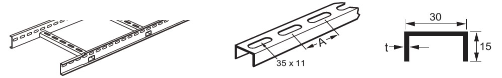
Integral couplers on straight lengths and fittings enable joints to be made quickly and easily, thereby reducing installation time. Rung spacing is 300 mm between centres. Standard radius for fittings is 300 mm.
Straight Section
| Width | Straight Lengths | Rung Details | |
|---|---|---|---|
| Rung Thickness (t) | Accessory Rung Pitch A | ||
| mm | m | mm | mm |
| 150 | 3 | 1.0(rung length up to 300)/1.5(rung length above 300) | 49.0 |
| 300 | 3 | 1.0(rung length up to 300)/1.5(rung length above 300) | 49.5 |
| 450 | 3 | 1.0(rung length up to 300)/1.5(rung length above 300) | 49.7 |
Coupler Set
These coupler sets are supplied in pairs with fasteners, required only where ladder has been cut to length. When joining a cut length to an uncut length or a fitting only one coupler is required.

Fastener Set
Fastener sets are supplied in packs, consists of M6×16 set screws, M6 nuts, M6 roofing washers, M6 shakeproof washers.
Fittings
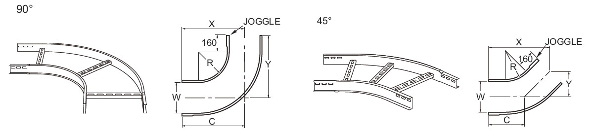
Flat bends
Flat bends are used to assist in the installation of a complete cable ladder run following a centre-line drawing.
- X = length of fitting from each ‘end’ of centre-line (not including integral coupler)
- Y = length from each ‘end’ of the fitting to the point at which the centre-lines intersect (not including integral coupler)
- C = length of the centre-line from each ‘end’ of the fitting to the point at which the centre-lines intersect (not including integral coupler)
| Width(W) | Radius(R) | Angle | X | Y | C |
|---|---|---|---|---|---|
| mm | mm | ゜ | mm | mm | mm |
| 150 | 300 | 90 | 534 | 534 | 534 |
| 300 | 300 | 90 | 609 | 609 | 609 |
| 450 | 300 | 90 | 684 | 684 | 684 |
| 150 | 300 | 45 | 537 | 223 | 315 |
| 300 | 300 | 45 | 590 | 244 | 346 |
| 450 | 300 | 45 | 643 | 266 | 377 |
Risers
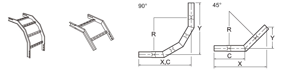
| Width(W) | Radius(R) | Angle | X | Y | C |
|---|---|---|---|---|---|
| mm | mm | ゜ | mm | mm | mm |
| 150 | 300 | 90 | 450 | 450 | 450 |
| 300 | 300 | 90 | 450 | 450 | 450 |
| 450 | 300 | 90 | 450 | 450 | 450 |
| 150 | 300 | 45 | 443 | 183.5 | 260 |
| 300 | 300 | 45 | 443 | 183.5 | 260 |
| 450 | 300 | 45 | 443 | 183.5 | 260 |
CLIR represents inside riser. CLIR will be changed to CLOR if inside riser is changed to outside riser.
Equal tees and 4 way crosspieces

| Width(W) | Width(W) | Equal Tees Width(X/Y) |
|---|---|---|
| mm | mm | mm |
| 150 | 300 | 534 |
| 300 | 300 | 609 |
| 450 | 300 | 684 |
T represents equal tee. CLT will be changed to CLX if equal tee is changed to 4 way crosspiece.
Reducers
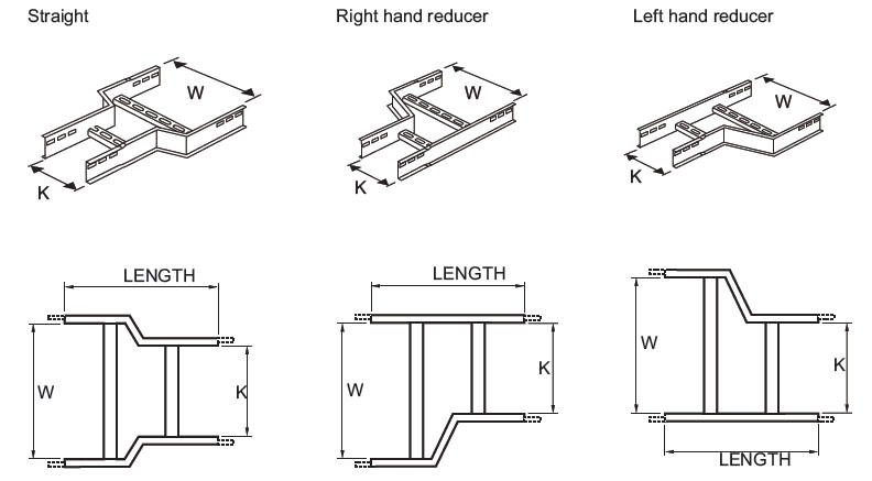
| Width(W) | Width(K) | Straight Reducer Length | Offset Reducer Length |
|---|---|---|---|
| mm | mm | mm | mm |
| 300 | 100 | 450 | 450 |
| 300 | 150 | 450 | 450 |
| 300 | 225 | 400 | 450 |
| 450 | 100 | 450 | 550 |
| 450 | 150 | 450 | 500 |
| 450 | 225 | 450 | 500 |
| 450 | 300 | 450 | 450 |
CLSR represents straight reducer. CLSR will be changed to CLLR if straight reducer is changed to left hand offset reducer. CLSR will be changed to CLRR if straight reducer is changed to right hand offset reducer.
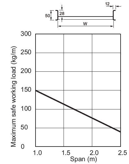
Loading Graphs
The loads shown on the graph are the safe recommended maximum loads that can be applied and must include wind, snow and any other external forces in addition to the cable load.
The graphs show the maximum load for ladder installed at a support spacing within its recommended range. When the graph line is above the intersection of the required load and span lines, the support equipment is suitable for use within those load and span conditions.
The graphs shown are for galvanised and deep galvanised finishes.