![]() Power Cables
Power Cables
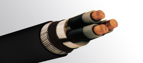
Three Core Cables to IEC 60502
APPLICATIONS
The three core cables are designed for distribution of electrical power with nominal voltage Uo/U ranging from 1.8/3KV to 26/35KV and frequency 50Hz. They are suitable for installation mostly in power supply stations, indoors and in cable ducts, outdoors, underground and in water as well as for installation on cable trays for industries, switchboards and power stations.
STANDARD:
IEC 60502 Part 1(1.8/3KV)
IEC 60502 Part 2(3.6/6KV to 18/30KV)
 |
 |
CONSTRUCTION:
Conductor: Plain annealed copper or aluminium complying with IEC 60228 class 1 or 2.
Conductor Screen: The conductor screen consists of an extruded layer of non metallic, semi-conducting compound applied on top of a semi conducting tape. The conductor screen is applied under triple extrusion process over the conductor along with the insulation and the insulation screen. The extruded semi-conducting compound is firmly bonded to the insulation to exclude all air voids and can be easily hand stripped on site. The conductor screen is not necessary for both PVC and EPR/HEPR insulated 1.8/3.6KV and 3.6/6KV cables.
Insulation: Insulation is of polyvinyl chloride (PVC) intended for 1.8/3.6KV and 3.6/6KV cables, cross-linked polyethylene compound (XLPE) or ethylene propylene rubber (EPR/HEPR).
Table 1. Insulation Thickness of XLPE or EPR/HEPR insulation
Nom. Cross Section Area |
Insulation Thickness at Nom. Voltage |
|||||||||
1.8/3kV(Um=3.6)kV |
3.6/6kV(Um=7.2)kV |
6/10KV(Um=12KV) |
8.7/15KV(Um=17KV) |
12/20KV(Um=24KV) |
18/30KV(Um=36KV) |
21/35KV(Um=42KV) |
26/35KV(Um=42KV) |
|||
mm2 |
mm |
mm |
mm |
mm |
mm |
mm |
mm |
mm |
||
XLPE/EPR |
XLPE |
EPR |
XLPE/EPR |
XLPE/EPR |
XLPE/EPR |
XLPE/EPR |
XLPE/EPR |
XLPE/EPR |
||
Unscreened |
Screened |
|||||||||
10 |
2.0 |
2.5 |
3.0 |
2.5 |
- |
- |
- |
- |
- |
- |
16 |
2.0 |
2.5 |
3.0 |
2.5 |
3.4 |
- |
- |
- |
- |
- |
25 |
2.0 |
2.5 |
3.0 |
2.5 |
3.4 |
4.5 |
- |
- |
- |
- |
35 |
2.0 |
2.5 |
3.0 |
2.5 |
3.4 |
4.5 |
5.5 |
- |
- |
- |
50 – 185 |
2.0 |
2.5 |
3.0 |
2.5 |
3.4 |
4.5 |
5.5 |
8.0 |
9.3 |
10.5 |
240 |
2.0 |
2.6 |
3.0 |
2.6 |
3.4 |
4.5 |
5.5 |
8.0 |
9.3 |
10.5 |
300 |
2.0 |
2.8 |
3.0 |
2.8 |
3.4 |
4.5 |
5.5 |
8.0 |
9.3 |
10.5 |
400 |
2.0 |
3.0 |
3.0 |
3.0 |
3.4 |
4.5 |
5.5 |
8.0 |
9.3 |
10.5 |
500 - 1600 |
2.2-2.8 |
3.2 |
3.2 |
3.2 |
3.4 |
4.5 |
5.5 |
8.0 |
9.3 |
10.5 |
Insulaton Screen: The insulation screen consists of an extruded layer of non metallic, semi-conducting compound extruded over the insulation of each core. The extruded semi-conducting layer shall consist of bonded or cold strippable semi conducting compound capable of removal for jointing or terminating. As an option, a semi-conducting tape may be applied over the individual cores or core assembly as a bedding for the metallic layer. The minimum thickness is 0.3 mm and the maximum resistivity is 500 Ohm-m at 90°C. The screen is tightly fitted to the insulation to exclude all air voids and can be easily hand stripped on site. The insulation screen is not necessary for both PVC and EPR/HEPR insulated 1.8/3.6KV and 3.6/6KV cables. The screen may be covered by semi conductive water blocking swellable tape to ensure longitudinal watertightness.
Inner Covering & Fillers: For cables with a collective metallic layer or cables with a metallic layer over each individual cores with additional collective metallic layers, semi conducting inner covering and fillers shall be applied over the laid up cores. The inner covering and fillers are made of non hygroscopic material like polypropylene, except if the cable is to be made longitudinally watertight. The inner covering is extruded in general but may be lapped if the interstices between the cores are filled.
The approximate thickness of extruded inner coverings is given in Table 2:
Table 2. Approximate thickness of extruded inner coverings
Ficititous
Diameter Over Laid Up Cores
|
Approx.
Thickress of Extruded Inner Covering
|
|
mm
|
mm
|
|
>
|
<
|
|
-
|
25
|
1.0
|
25
|
35
|
1.2
|
35
|
45
|
1.4
|
45
|
60
|
1.6
|
60
|
80
|
1.8
|
80
|
-
|
2.0
|
*The approximate thickness of lapped inner coverings shall be 0.4mm for fictitious diameters over the laid up cores up to and including 40mm and 0.6mm for larger diameter.
Metallic Layer: The metallic layer may be applied over the individual cores or the core assembly collectively. The following types of metallic layers are provided:
1) Metallic Screen
2) Concentric Conductor
3) Metallic Sheath
4) Metallic armour
The metallic screen shall consist of either copper tapes or a concentric layer of copper wires or a combination of tapes and wires. The concentric conductor is applied directly over the inner covering. The metallic sheath consists of lead or lead alloy applied as a tightly fitting seamless tube. The metallic armour consists of either flat wire armour, round wire armour, and double tape armour.
Table 3. Minimum Total Cross Section of Metallic Screen
Nom.
Cross-SectionArea of Cable
|
Min.
Cross-Sectionof Metallic Screen
|
DC Resistance of the
Copper Wire Screen
|
mm2
|
mm2
|
mm
|
up to
120
|
16
|
1.06
|
150-300
|
25
|
0.72
|
400-630
|
35
|
0.51
|
800-1000
|
50
|
0.35
|
Separation Sheath (for armoured cable): The separation sheath comprises a layer of extruded PVC, PE or LSZH applied over the laid up cores under the armour. PVC is normally of grade ST2 and PE of grade ST7. The nominal thickness is calculated by 0.02Du + 0.6mm where Du is the fictitious diameter under the sheath in mm. For cables without a lead sheath, the nominal separation sheath thickness shall not be less than 1.2mm. For cables where the separation sheath is applied over the lead sheath, the nominal separation sheath thickness shall not be less than 1.0mm.
Tabel 4. Separation Thickness Cores Diameter Approx. Thickress of Inner Sheath
Cores
Diameter
|
Approx.
Thickress ofInner Sheath
|
|
mm
|
mm
|
|
>
|
<
|
|
35
|
45
|
1.4
|
45
|
60
|
1.6
|
60
|
80
|
1.8
|
80
|
-
|
2.0
|
Lapped Bedding (for armoured lead sheathed cable): The lapped bedding applied to the lead sheath consists of either impregnated/synthetic compounded paper tapes or a combination of two layers of these paper tapes followed by a few layers of compounded fabulous materials. The thickness is around 1.5mm.
Armour (for armoured cable): The armour is applied over the inner covering helically. It consists of either flat galvanized steel wire armour (strip), round galvanized steel wire armour, and double steel tape armour.
Table 5. Round Armour Wire Diameter
Fictitious Diameter Under
the Armour
|
Armour
Wire Diameter
|
|
mm
|
mm
|
|
>
|
<
|
|
-
|
10
|
1.25
|
10
|
15
|
1.25
|
15
|
25
|
1.6
|
25
|
35
|
2.0
|
35
|
60
|
2.5
|
60
|
-
|
3.15
|
Table 6. Armour Tape Thickness
Fictitious Diameter Under
the Armour
|
Galvanized
Steel / Steel
|
Aluminum
/ Aluminium Alloy
|
|
mm
|
mm
|
mm
|
|
>
|
<
|
|
|
-
|
30
|
0.2
|
0.5
|
30
|
70
|
0.5
|
0.5
|
70
|
-
|
0.8
|
0.8
|
For flat wire armour and fictitious diameter under the armour greater than 15mm, the nominal thickness of the flat steel wire diameter shall be 0.8mm, Cables with fictitious diameter under the armour up to and including 15mm, flat wire armour will not be used. The tape armour is applied helically in two layers so that the outer tape is approximately central over the gap of the inner tape. If tape armour is used, the inner covering shall be reinforced by taped bedding.
Over Sheath: Overall sheath comprises a layer of extruded either thermoplastic compound (PVC ST3 type or PE ST7 type) or elastomeric compound (polychlorprene CSP or chlorosulfonated PE). The nominal oversheath thickness is calculated by 0.035D+1 where D is the fictitiuous diameter immediately under the oversheath in mm. For unarmoured cables and cables with the oversheath not applied over the armour, metallic screen or concentric conductor, the nominal oversheath thickness shall not be less than 1.4mm. And for cables with oversheath applied over the armour, metallic screen or concentric conductor, the nominal oversheath thickness shall not be less than 1.8mm.
PHYSICAL PROPERTIES:
Operating Temperature: up to 70°C (PVC insulation); up to 90°C (XLPE or EPR
insulation)
Short Circuit Temperature( 5 seconds maximum duration ): 140-160 °C (PVC insulation); 250°C (XLPE or EPR insulation)
Bending Radius: 15 x OD
Table 7. Nominal /Operating /Testing Voltages:
Rated Voltage Uo/U
|
Operating Voltage (Um)
|
Testing Voltage (rms)
|
1.8/3KV
|
3.6KV
|
6.5KV
|
3.6/6KV
|
7.2KV
|
12.5KV
|
6/10KV
|
12KV
|
21KV
|
8.7/15KV
|
17.5KV
|
30.5KV
|
12/20KV
|
24KV
|
42KV
|
18/30KV
|
36KV
|
63KV
|
21/35KV
|
42KV
|
73.5(53)*KV
|
26/35KV
|
42KV
|
91(65)*KV
|
*21/35KV and 26/35kV power frequency voltage test can be made under the following conditions: 2.5Uo x 30mins or 3.0Uo x 15mins. Numbers in brackets refer to the test values for 3.0Uo x 1.5mins.
Three Core 3.8/6.6KV (Um=7.2KV)
Three Core 8.7/15KV (um=17.5kV)
Three Core 1.8-3KV(Um=3.6KV )to 26-35KV(Um=42KV) XLPE Insulation
Three Core 1.8-3KV(Um=3.6KV) to 26-35KV(Um=42KV) EPR Insulation