| Fire Resistant Cable | |||
![]() Fire Resistant Cable
Fire Resistant Cable
300V Mica+LSZH Insulated & LSZH Sheathed Fire Alarm CablesJE-H(St)H…Bd FE180 E90. (CU/MICA+LSZH/OSCR/LSZH 300V Class 1 )
|
|||||||||||||||||||||||||||||||||||||||||||||||||||||||||||||||||||||||||||||||||||||||||||||||||||||||||||||||||||||||||
Circuit Integrity |
IEC 60331-23; BS 6387 CWZ; DIN VDE 0472-814(FE180); |
System circuit integrity |
DIN 4102-12, E90 depending on lay system |
Flame Retardance (Single Vertical |
EN 60332-1-2; IEC 60332-1-2; BS EN 60332-1-2; |
Reduced Fire Propagation |
EN 60332-3-24 (cat. C); IEC 60332-3-24; BS EN 60332-3-24; VDE 0482-332-3; NBN C 30-004 (cat. F2); NF C32-070-2.2(C1); CEI 20-22/3-4; EN 50266-2-4*; DIN VDE 0482-266-2-4 |
Halogen Free |
IEC 60754-1; EN 50267-2-1; DIN VDE 0482-267-2-1; CEI 20-37/2-1 ; BS 6425-1* |
No Corrosive Gas Emission |
IEC 60754-2; EN 50267-2-2; DIN VDE 0482-267-2-2; CEI 20-37/2-2 ; BS 6425-2* |
Minimum Smoke Emission |
IEC 61034-1&2; EN 61034 -1&2; DIN VDE 0482-1034-1&2; CEI 20-37/3-1&2; EN 50268-1&2*; BS 7622-1&2* |
No Toxic gases |
NES 02-713; NF C 20-454 |
Note: Asterisk * denotes superseded standard.
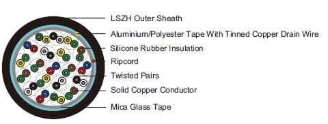
CABLE CONSTRUCTION
Conductors: Solid annealed bare or tinned copper sized 0.8mm as per class 1 of VDE 0295/IEC
60228.
Fire Barrier: Mica glass tape.
Insulation: Thermoplastic LSZH compound HI1 as per DIN VDE 0207-23.
Cabling Elements: Insulated cores are twisted to form pairs with varying lay length to minimize
crosstalk. Two-pair cable had four cores laid in quad formation.
Cabling: Pairs are cabled together. In cables with 8 pairs or more, 4 pairs are assembled to form a
bunch, the bunches are then cabled together.
Cable Core Assembly: The twisted pairs are stranded to the core in layers.
Core Wrapping: One or more non hygroscopic polyester tapes are helically or longitudinally laid with
an overlap prior to sheathing.
Screen: A laminated Aluminum/Polyester tape in contact with solid copper 0.6mm or 0.8mm drain
wire.
Ripcord: Nylon ripcord may be placed parallel to the cores to facilitate sheath removal.
Drain Wire: A solid tinned earth/continuity wire shall be laid longitudinally for screened cables.
Outer Sheath: Thermoplastic LSZH compound HM2 as per DIN VDE 0207-24 .
COLOUR CODE
Quad colour in each bundle:
Pair 1: Blue-Red
Pair 2: Green-Yellow
Pair 3: Green-Brown
Pair 4: White-Black
The individual bundles are identified by a numbered helix.
TYPE CODE
JE- Fire alarm cable (St) Static shield of Aluminum tape
H Halogen free & zero halogen FE180 Insulation integrity (950°C 180 minutes)
Bd Unit stranding E90 90 minutes circuit integrity
Physical AND THERMAL PROPERTIES
Temperature range during operation (fixed state): -30°C – +90°C
Temperature range during installation (mobile state): -20°C – +50°C
Minimum bending radius: 8 x Overall Diameter
Electrical PROPERTIES
Nominal Conductor Diameter |
mm |
0.8 |
Conductor Size |
mm2 |
0.5 |
Maximum Conductor Resistance @20°C |
Ω/km |
34.6 |
Maximum Loop Resistance @20°C |
Ω/km |
73.2 |
Minimum Insulation Resistance @500V DC @20°C |
MΩ.km |
100 |
Maximum Average Attenuation @0.8KHz |
dB/km |
1.1 |
Average Mutual Capacitance |
nF/km |
120 |
Capacitance Unbalance K1 @0.8KHz pair-to-pair |
pF/100m |
200 |
Working Voltage |
V |
300 |
Nominal Insulation Thickness |
mm |
0.4 |
Nominal Insulated Conductor Diameter |
mm |
1.6 |
CONSTRUCTION PARAMETERS
VDE CODE: JE-mH(St)H…x2x0.8 Bd FE180 E90 /JE-H(St)H…x2x0.8 Bd FE180/E90 BMK*Cable Code |
No. of Pairs |
Nominal Insulation Thickness |
Nominal Sheath Thickness |
Nominal Overall Diameter |
Approx. |
|
|
mm |
mm |
mm |
kg/km |
0.8mm Conductor, 1.6mm Insulated Wire |
|||||
JE-H(St)H...2x2x0.8 Bd FE180/E90 BMK* |
2 |
0.4 |
1.0 |
12.8 |
177 |
JE-H(St)H...4x2x0.8 Bd FE180/E90 BMK* |
4 |
0.4 |
1.0 |
16.3 |
284 |
JE-H(St)H...8x2x0.8 Bd FE180/E90 BMK* |
8 |
0.4 |
1.0 |
20.3 |
447 |
JE-H(St)H...12x2x0.8 Bd FE180/E90 BMK* |
12 |
0.4 |
1.2 |
23.9 |
615 |
JE-H(St)H...16x2x0.8 Bd FE180/E90 BMK* |
16 |
0.4 |
1.2 |
26.6 |
756 |
JE-H(St)H...20x2x0.8 Bd FE180/E90 BMK* |
20 |
0.4 |
1.2 |
29.4 |
921 |
JE-H(St)H...32x2x0.8 Bd FE180/E90 BMK* |
32 |
0.4 |
1.4 |
30.7 |
1074 |
JE-H(St)H...40x2x0.8 Bd FE180/E90 BMK* |
40 |
0.4 |
1.4 |
33.6 |
1278 |
JE-H(St)H...52x2x0.8 Bd FE180/E90 BMK* |
52 |
0.4 |
1.6 |
43.7 |
2011 |